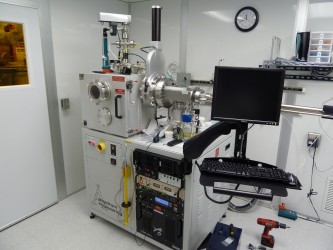
Amod evaporator

Description

The Amod evaporator is a computer controlled, load locked evaporation system. This tool is equipped with a 7cc, 4-pocket telemark ebeam system and two resistive sources. Each source is shuttered and has an independent crystal monitor. The system also has a glow discharge source in the main chamber and an RGA detector.


Processes

Aluminum Thin Film

  • Thin films of aluminum can be deposited via sputtering or evaporation.


Chrome Thin Film

  • Chrome RF sputter deposition.

dep rate= 9.4nm/min, power=400W RF, pressure=10mT Argon, substrate height =120


Gold Thin Film

  • Thin films of gold can be deposited via sputtering or evaporation. Ebeam and resistive thermal evaporation are available.


Silicon Dioxide Thin Film

  • Thin films of silicon dioxide can be deposited via sputtering.


Titanium Thin Film

  • Thin films of titanium can be deposited via sputtering.


Operating Manual 

*Note that the instructions below may not contain the most recent updates. Please refer to the manuals printed and posted at the equipment.

Safety

  • This tool contains high voltage sources. Be sure to ground sources before working inside the tool.
  • Do not go behind the tool or attempt to open covers.
  • Avoid pinching your fingers in the chamber door or with the load lock lid.
  • Use caution to avoid bumping your head when working in the chamber or around the transfer arm.
  • If the crucible is uncomfortably bright, wear the green glasses located on top of view port.
  • The inside of the chamber can get hot during certain depositions. Use care when loading and unloading your samples and deposition materials.

Allowed Materials and Processes.

This tool is primarily used for metal depositions, for example titanium, chromium, gold, aluminum, copper, and silver, among others. Please work with staff before depositing any materials.

Restricted Materials and Processes

  • Do not attempt to make your own recipes without extensive training and permission from the lab manager.
  • Contact the lab manager for higher value evaporation sources such as gold and silver since they are not stored in the lab.
  • Do not edit Sweep Patterns 1 through 4 without training and permission from the lab manager.
  • Watch the crucibles as the beam turns on and increases in power. If the beam is out of alignment or anything else seems awry, abort the process.
  • Do not let the material in the crucible get so low that the beam hits the liner. If the beam burns through the liner and through the hearth, it will cause major equipment damage.
  • Do not leave the deposition to run for more than about ten minutes without checking the tool to make sure it is operating properly.
  • If anything goes wrong during the deposition process, press the “Abort Process Button.”

1.Check reservations and make one.

 
 2.Check tool status and configuration.
  1. Visit: http://www.mmf.montana.edu/equipment-status.html.
  2. Request different targets or shields at least 2 weeks in advance by emailing the labmanager and mmfstaff@montana.edu.


3.Check lab status
  1. Check that the N2 bottle pressureis above 400 PSI.
  2. Check that N2 is on forlab.
  3. If your process needs oxygen or argon, such as a Glow Discharge, check theO2 orArbottle pressures.


4.Log into SUMS
 
 
5.Equipment checks
  1. Check deposition chamber pressure
    1. It the AMOD hasnot been usedfor several hours, it shouldbe <8e-7.
    2. If the AMOD has been used recently, it should be <5e-6 and decreasing.
  2. Checkthat thecryo temperatureis < 15K.


6.Check the installeddeposition materials.If your materialsare loaded, you do no not need to vent the chamber and can skip to step 15.
  1. Click the “Edit” button below “Shutter Controls” to view which deposition materialsareloaded.Note that you always need to check that the recipe and pocket number match upfor your deposition.


7.Vent the chamber by first unhooking the chamber door latchesand then pressing “Auto Vent”followed by“Start Selected Cycle."On the “AUTO VENT PUMP AND PURGE"screen, click“Start.” You do not need to enable pump and purge cycles unless you are running a non-standardmaterial and you have discussed the procedure with staff.
 
 
8.Ground the chamber before touching anything inside – touch the grounding rod to theE -beamsource and twocopper thermal sources.
 
 
9.Load desired sources
  1. Switch the pocket controller to manual mode.
  2. Toggle to the desired pocket using CWW/CW switch.
  3. On the "EDIT"button under SHUTTER CONTROLS,click the “OPEN” button tothe left of the “SHUTTER#1/SOURCE#1” tab to move the shutterout of the way.
  4. If you need to fill anew crucible:
    1. Reference Telemark crucible liner guide to determine compatible source andcrucible materials:
    2. Fill the crucible ¾ full of source material. Ask staff for standard weights.
  5. Vacuum out the pocket and make sure the deposition that has built up is not so greatthat it obstructs the crucible.If the build up is substantial, work with staff to clean thepockets.
  6. Load crucible into the pocket.
  7. Switch the pocket controller back to Auto.
  8. Record material and respective pocket on “Shutter Controls”page.


10.Check sensor readings on Sigma software through “View” and “Sensor Readings”.
 
 
11.Replace any sensors with “Life” reading below 80% withnewquartz crystals.
  1. New sensors are in the top drawer of the blue cabinet to the right of the AMOD.
 
12.Check that the mirror is in place and that you can see the deposition materials.
  1. If themirror is no longer reflective and you cannoteasily see thecrucible liner, replacethe mirror. New mirrors are inthe top drawer of the blue cabinet to the right of theAMOD.
 
13.On the “EDIT” button under SHUTTER CONTROLS, click the “CLOSE” button to the leftof the “SHUTTER#1/SOURCE#1” tab to move the shutter back in place.
  1. Look inside chamber and check that Shutter #1 has closed.
 
14.Wipe the o-ringand sealing surface with a dry wipe.Re-latchthe chamber door and beginevacuating the chamber with “Full Pump Down”followed by “Start Selected Cycle”.
  1. It takes around 1 hour and 45 minutes for the AMOD chamber to fully pump down.


15.Vent the load lock with “LL Auto Vent” on system interlock software. Then hit “Start Selected Cycle”.
 
 
16.Prepare sample
  1. Use screws orvacuum-ratedKapton tape to hold your sample to the sample holder.
    1. If you are using tape, make sure to cover the open screw holes with tape.
    2. If you are using screws, donot over tighten them because they can crack orbreak your samples.


17.Load sample and stage into load lock.Then shut load lock lid.
a.Check that the sampleholder has a ~1 cm gap from the right side of the fork.
 

18.
Pump down the load lock with “LL Full Pump Down”. Then hit “Start Selected Cycle”.
 
 
19.Check stage rotation and height
  1. The orange stage rotation knob should be at ~11 o’clock and the switch should beflipped up unless you do not want to use stage rotation.


20.Choose recipein Sigma software
  1. Open the database where your recipe is loadedand select a process.
  2. Editthefilm thickness.
  3. Verify that the pocketnumber matches the source listed on the Edit Shutter Controls page.


21.Once the load lock is <5e-5, use transfer arm to load stage into the chamber
  1. Click "Load Lock Gate Valve and click "Open".
  2. Verify that the chamber light is on. If it is not, turn it on using the light bulb button on the AMOD software.
  3. While looking through the site glass on the main chamber, rotate the load lock knob counterclockwise to move the fork into the chamber.
  4. Line up the plug with the socket and use the sample stage rotation knob to align the screw on the plug with the slot in the socket.
  5. Use the black rocker switch on top of the chamber to lower the socket over the plug.Ifyou see the fork or sample bending downward, stop! Raise the socket and start over.Never put downward pressure on the fork.
    1. Lower the socket to the spot on the plug where there are numerous scuff/linemarks.This spot is a different color than the rest of the plug.
  6. Rotate the socket clockwise (from top vantage) to pick up the sample holder, and then raise the sample holder off the fork.
  7. Remove the fork completely from the chamber.
  8. Close the load lock gate valve. You cannot close the load lock gate valve if the fork is not in its home position all the way tothe right.
  9. Turn off the light.


22.Once the chamber is <1e-6, begin and monitor the deposition.
  1. Checkagain that the desired recipeis selectedfrom appropriate user database. Do notedit recipes in the “MMF -Standard -Recipes.mdb” database,except for the finalthickness.
  2. Verify again that that the index in the layer tab matches the pocket number in theAngstrom software.
  3. Use Sigma software to initiatethe deposition by pressing “Start Process.”
  4. Verify that the LEDbelow “Pocket” on the Sigma CI-100 Indexer reads the correctpocket. (i.e. Verify that the pocket moved to the correct location.)
  5. Monitor the power graph in the Sigma software by pressing “View” and then “PowerGraph.” Verify that the power is ramping up.
  6. Monitor the beam position during the ramps to make sure that the beam is centered inthe pocket.
  7. Switch between monitoring the power and the rate graphs during the ramp and holdsteps. Note any anomalies and abort the process if anything is happening outof theordinary.
  8. Monitor the deposition through the viewing window periodically.
  9. When the process is complete, wait for the deposition material to stop glowing beforestarting the next process. For example, if you are depositing a Ti/Au layer, wait for theTi to stop glowing completely before running the Au process. Typically,that will beabout 3- 5 minutes.
  10. If you are venting the main chamber, waitfor the source to cool for at least 5 minutesbeyond the power ramp down.


23.Unload the sample
  1. Make sureTransfer Arm is pushed all the way to the rightand raise the stageso the 25mm mark is adjacent the hole on the stationary rod.
  2. Click “Load Lock Gate Valve”, then click “Open”.
  3. Rotate the load lock knob counterclockwise to move the fork into the chamber.
  4. Once the fork is directly underneath the stage, rotate the stage using the socket rotationknob, so that the two flat edges of the stage are in line with the two prongs of the fork.
  5. Using the black rocker switch, slowly lower the stage until it contactsthe fork.
  6. Continue to lower the socket to the spot on the plug where there are numerousscuff/line marks.
    1. Ensure that when you are lowering thesocket/stage,it does not bend the forkdownward.
  7. Rotate the stage counterclockwise (from the top) using the socket rotation knob tounhook the stagesocketfrom the plug.
  8. Using the black rocker switch, slowly raise the plug out of the stage socket.The stagesocket and the plug should become completely separated.
  9. Rotate the load lock knob clockwise to move the fork out of the chamber and into theload lock.
    1. Make sure the Transfer Arm is all the way to the right
  10. Click “Load Lock Gate Valve”, then click “Close”.
  11. If you want to open the load lock door to remove the stage, click “LL Auto Vent”, thenclick “Start SelectedCycle”.
  12. Remove stage and close load lock door.


24.If you want to load another sample, go to step 14, if you are finished, continue to step 25.
 
 
25.Remove substrate from stage and replacestage in Load Lock Chamber.Close Load LockChamber lid and click“LL FullPump Down”, then click “Start Selected Cycle”.
  1. Make sure chamber light is off.


Troubleshooting

  • Chamber will not vent.
    • Ensure lab N2 is on.
    • Ensure lab N2 bottle has enough pressure.
  • Sigma software faults.
    • Pressure exceeds base pressure necessary for deposition.
      • Off gas from melting source increases chamber pressure.
    • Pocket controller is on wrong pocket and in manual mode.
    • Recipe times out from failing to reach desired deposition rate.
  • LL Full Pump Down not completing
    • Check that the TransferArm is pushed all the way to the right. You can check if it isall the way to the right by looking atthe Deposition System Page and seeing if thedot by the Transfer Arm is red or green. Green means it is pushed all the way to theright, red means it is not.
  • "Source Index timeout on Output 1. Layer stopped!"
    • Switch CI- 100 Indexer to Manual, and rotate pocket number to a different pocketnumber than you are trying to use. Switch back to Auto. Click “OK”, then ontheSigma Software screen, click “Next Layer",then click “Start Process”.
  • Stage stops spinning midway through deposition
    • Make sure nothing is touching the rotation knob.
  • Substrate shutter not moving out of the way during deposition
    • Restart computer and try again.