Photo of 
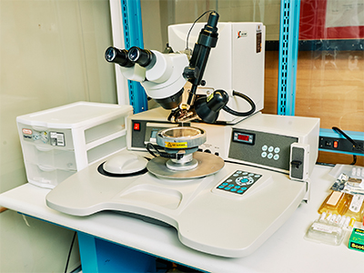
K&S 4523AD Wedge Bonder

Description 

The K&S 4523AD is a wedge bonder typically used for making electrical connections between MEMS or IC die and external packaging. Manual, semiautomatic and automatic operating modes can be selected for the required application.

Automated table motion with kink and reverse motion allows the user to create specific bond profiles.

MMF stocks 25μm (1.0 mil) aluminum and gold wire with wedges for 45° feed and vertical feed (deep access).


Operating Manual

*Note that the instructions below may not contain the most recent updates. Please refer to the manuals printed and posted at the equipment.

Wire bonding is a fundamental technique in microfabrication and electronics assembly, involving the connection of semiconductor devices to substrates using fine wire. In the wedge bonding manual process, a wedge-shaped tool is used to bond the wire between a bonding pad on the semiconductor device and a substrate. This process is crucial in various applications such as semiconductor packaging, IC assembly, MEMS devices, and optoelectronic devices like LEDs. The process involves preparation, loading, alignment, bonding, wedge formation, inspection, testing, and potential post-bonding processes like encapsulation. Following this manual ensures reliable electrical connections and high-quality wire bonds suitable for a wide range of semiconductor applications.

Wear shoe covers, lab coat, hand gloves before entering the main workspace.

Keep hands out of the work holder while the Bonding tool is in operation.

Use tweezers to place the sample as the work holder is a heated stage.

  • 1 mil aluminum wire
  • 1 mil gold wire
  • 1x10 mil gold ribbon
  • Others available on request and with lead time
  • Make sure samples are clean and dry.

Ensure the clamp is closed before attempting to bond.

  1. Startup
    1. Plug the Orange extension cord into the outlet on the ground, and turn on the main power switch (5).
    2. Select “Enable” password mode. Select “Engineering,” Enter 3519.
    3. Check the workholder temperature. Use the “set” button on the eliwell controller and the up and down arrows to change the setpoint for your application. Typically, 150C.
    4. Lower the stage by turning the work holder base CCW and set holder aside. Make sure the work holder is at its minimum height.
  2. Install the wedge (if required).
    1. Reference Table 5-1 in User manual for compatible wedges.
    2. If you are switching wires and want a different wedge, you will need to remove the old one and install the appropriate one.
    3. Move the workholder out of the way.
    4. While holding your hand underneath the wedge or a wipe, unscrew the wedge currently installed.
    5. Place the hex wrench in the set screw, then using the holder jig to set the height while tightening the set screw.
    6. Press the “TEST” button to ensure good setup. If it lights up green, it is good to go.
  3. Wire Loading: Load the appropriate wire. (The wire bonder is set up with a vertical feed of wire)
    1. Ensure that bonding head is in the Reset position (up).
    2. Open the clamp manually by pulling the clamp plunger towards you and rotating the clamp plunger slightly counterclockwise to lock it in the open position.
    3. Hold the wire about 25 mm (1") from the end and feed the wire into the vertical hole of the wedge until it protrudes from the hole at the bottom; Ensure that the wire is loaded from the front side of the spool, through the wire guide and the clamp, to the wedge.
    4. Pull a small excess ~3 mm of wire out of the bottom of the bonding tool and thread the tip. The hole to aim for is not visible from the microscope, pull a small section of ribbon out and be sure it’s straight. Aim for very slightly above the tip of the wedge.
    5. When feeding a new wire into the wedge/capillary, tear off a small piece of the wire lead to create a sharp point at the end of the wire. This makes it much easier to insert the wire into the wedge/capillary hole.
    6. Release the clamp plunger to close the clamp.
    7. Bond off the excess wire.
  4. Height Adjustment *** insert step of loading sample.
    1. Place the sample on work holder using tweezers.
    2. Move the work holder on the workstation.
    3. Press and release the RIGHT button of the mouse. The bonding head drops to its lowest position and remains there.
    4. Focus the substrate by moving the work holder upward turning the lower silver dial just above the Work-table (8). Keep raising the work holder until the wedge just touches the lowest bonding point.
    5. Press the RESET switch to return the bonding head to the Reset position.
    6. Set this “SEARCH HEIGHT” along with POWER, TIME, FORCE etc. for both 1st and 2nd bond depending on your substrate and wire type.
    7. Save the parameters to any of the available program numbers.
    8. In the future, you can just load your saved program to work with those parameters.
  5. Operation (Semi-Auto Wedge Bonding-90o Wire Feed)
    1. Set the system to SEMI AUTO mode.
    2. Set the POWER, TIME, and FORCE bonding parameters for the first and second bonds if you are a first-time user. Or load your saved program. See Fig 2 for MMF Recommended Parameters.
    3. Set the LOOP height; This is the height the bonding wedge will go to after the first bond.
    4. Set the TAIL parameter.
    5. Adjust the SEARCH HEIGHT for the first bond if necessary. (This depends on your substrate.)
      1. Make sure the bonding head is in Reset position.
      2. Move over the first bond pad and hold down the RIGHT mouse button.
      3. Adjust the SEARCH height until the bonding tip is just above the bond pad.
    6. Release the RIGHT mouse button to make the first bond.
    7. After the first bond, the bonding head moves to the LOOP height. Adjust the loop height if needed.
    8. Adjust the SEARCH height for the second bond following the same procedure as in 2.5.
    9. Bonds are made by holding the RIGHT mouse button to lower the bonding head to the SEARCH height, positioning the bonding head by moving the mouse, releasing the mouse button to perform the bonding action.
    10. Start with the bond pad that is closest to you. Because, after the first bond, the bonding head will move away from you to 2nd bond position maintaining the loop height and STEP you set.
  6. Shutdown
    1. Press Reset button to keep the bonding head in Reset position.
    2. Move the work holder away form the workstation.
    3. Turn off the heater and light.
    4. Remove the substrate form the work holder using the tweezers.
    5. Unload your wire and clean the workspace.
    6. Turn off the main power switch of the wire bonder.
  • The first step of making a bond is holding the RIGHT mouse button to lower the bonding head to the SEARCH height. Second step is releasing the RIGHT button. Thus, a bond will form immediately after releasing the button. If you accidentally press the RIGHT mouse button and you do not want to make the bond at that unwanted spot, do not release the button. Instead, hold the RIGHT button and press the RESET button simultaneously.

The heater will sometimes overshoot its setpoint prior to stabilizing. Give it time and allow it to come back down.

  • If mouse is not responding, try clicking the “manual” button on the controls.


Parameters:

Au that you are bonding to dictates all those parameters. Messing around with different Au, two different golds, performed better super high, those on could ruin the tool, so high. Recommend using, 28.

Parameters, change power/time/force depending on what I’m seeing. Force, bond is indenting too much, lower force, no pressing to same level, raise it. Time spent vibrating/bonding. Power is the intensity of vibration. Don’t mess around with kink, reverse or y speed very often. For controlling shape of the loop. The second bond typically needs more power than the first. Tear, needs to be a bit stronger. Change tail/tear. Tear with table tear mode. Movement, size using to tear it. Found a good one for our usage.

Little set the hex in the hold, leave it, it will stay. Use tool to set tip height. Press and hold test to see if it stays on.

Install spool. Ribbon comes down in the front. Cut it at the last kink. Makes threading a lot easier. Rest it on the back clamp while threading.

Thread through tip, have about 2-3 mm spare, scissors for cutting wire.

Note: These are simply a starting place, these will change depending on your application (metalization, board material, etc.)


25um Au Wire

1x10 mil Au Ribbon


Notes

SEARCH 1

4

4


Start high, adjust based on height

POWER 1

2

6


TIME 1

4

6.5


FORCE 1

1.5

3


STEP

2.5

2


KINK

1.5

1.5


REVERSE

2

2


YSPEED

1

4


LOOP

4

3


SEARCH 2

4

4


POWER 2

1.5

6


TIME 2

4

3


FORCE 2

2

6


TAIL

5

6


TEAR

5

6.5


MODE

Table Tear

Table Tear


TIME

Long

Long


AUTO

Off

Off


Fig. 2 MMF Recommended Parameters

Fig. 2 MMF Recomended Parameters

Fig. 3 1x10 mil Minitab Experiment

Fig. 3 1x10 mil Minitab Experiment