Photo of a 
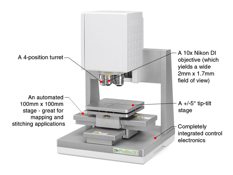
Filmetrics Profilm 3D optical profilometer

Description

The filmetrics profilm 3d optical profilometeruses state-of-the-art white light interferometry(WLI) to measure surface profiles and roughness down to 0.05µm; adding the low-cost PSI option takes the minimum vertical feature size down to 0.001µm.

Other Features

  • A free online analyzer for images such as profilometer and AFM
  • Intuitive Analysis Software
  • All 47 standard ASME/EUR/ISO roughness parameters
  • Multiple Step-height techniques: line, rectangle, and histogram
  • Roughness and waviness cutoff filter
  • Bearing ratio
  • Spatial and FFT filtering
  • Volume calculation
  • Form removal
  • Particles/Grains

Operating Manual

*Note that the instructions below may not contain the most recent updates. Please refer to the manuals printed and posted at the equipment.

  • To avoid electrical shocks, do not use the system if it is missing panels and electrical equipment is exposed.
  • Do not have your hands near the tool when the stage or optical head is moving.

Max substrate size: 100mm+ in diameter and up to 5 mm in height.

Do not place wet or dirty substrates on the stage.

  • Never bump the objective into anything.
  • Do not change the zero position in the software.
  • Verify that you will not hit the sample when rotating the objectives.
  • Verify that you will not hit the sample if you enter a Current Position in the Focus tab or for X and Y in the X-Y Stage tab Move To box.
  • The 50x objective working distance (WD) is 3.4 mm. The z-zero position is not set at zero from the stage to help avoid bumping the objective. With a normal silicon wafer, the z height in the software will read close to 1.5 mm when using the 50x objective.
  • 5x objective working distance (WD) is 7.4 mm. Do not turn the two silver knobs on the 5x objective. With a normal silicon wafer, the z height in the software will read close to 5.5 mm when using the 5x objective.
  • You should not have to adjust the stage tilt very much if at all. If you find you need to, contact staff to get help.
  • Do not adjust the mirror on the 5x objective without explicit permission.
  1. Turn on/wake up the computer and login. The password for BZ-ECE-PROFILM\Operator1 is “filmetrics”. You may also login using your NetID and password to the MSU domain.
  2. If it is not on, turn on the Accurion vibration isolation table with the switch on the back. Make sure the blue ISOLATION LED is lit and stable. If it does not turn on or does not stop blinking after thirty seconds, press the START/STOP button. If it still does not turn on, request help from staff.
  3. If it is not on, turn on the Profilm3D using the power switch on the back.
  4. Open the Profilm software from the Desktop and wait for the system to initialize. The measurement head will move up and down and the stage will move to the back left and then back to the center. Stay clear during these operations.
  5. After ensuring that the stage is empty, click the Load/Unload button to move the stage out from under the objectives.
  6. Load your sample on the stage and verify that the objectives will not hit the sample when you move the stage back to the central position.
  7. Navigate so the sample is under the objective using the arrows in the X-Y Stage area. Alternatively, press the white circle in the center of the arrows in the X-Y Stage tab to bring the stage back to 0, 0.
  8. Use the arrows in the X-Y Stage tab to navigate the objectives over a feature of interest.
  9. Use the z-arrows in the Focus tab to bring the sample into focus. You will likely have to move the stage back and forth to find your features while you adjust the z height. With a silicon wafer, the Current Position will read about 1.5 mm when using the 50x objective and it will read about 5.6 mm with the 5x objective. Focus the fringes on the lowest part of your sample.
    1. If your samples are flat and thin enough that there is not a concern of hitting the sample, using the AutoFocus button is a convenient way to set the focal plane.
  10. In the Image Intensity window, make sure the slider is at 50% or greater.
  11. Set up your scan.
    1. Set the backscan to move down some number of micrometers from current focus z height.
  12. Click start. Avoid movement while the tool finishes measuring.
  13. If your scan is slanted, try these options:
    1. Click the “Flatten” button at the top of the screen. A new window will pop up and click “Normal plane” in the Subtract Least-Squares Fit of Shape Selected Below box. Then click “OK” and the image should flatten out.
    2. Click the “Flatten” button at the top of the screen. A new window will pop up and click “Ignore Entire Image” in the Define Region Used When Fitting Shape (shown in Starting Image) box. Then you can select which shape type you want to use on the left hand side, your options are Rectangle, Polygon, and Circle. Adjust shape size to fit your features and place them in an area you know is flat. Then click “Use Selected Region”. Ifsa you want to use multiple shapes in multiple flat regions, move shape and repeat process.
  14. Step height
    1. Click the “Step Height” measurement box in the upper left corner of the screen.
    2. There are multiple options for measuring step height which include: Line, Rectangle, and Histogram.
    3. Line:
      1. Adjust red line on left side of screen in the Top View area to the section you want to measure.
      2. Incomplete...needs to be finished
    4. Rectangle:
      1. Resize yellow box in the Top View area to completely encompass step height you want to use. This method is best used with one step rather than measuring multiple steps.
      2. Ensure red dotted line is along the step height that is going to be measured. Click “next”.
      3. Then adjust green boxes to completely encompass each side of the step. Click “Finish”.
    5. Histogram
      1. Click “Histogram” tab in the Step-Height measurement box and results will pop up automatically.
      2. Move the red line on the Histogram box to adjust for outliers.
    6. If you have done
  1. Finish
    1. Enter 8 mm in the Current Position under the Focus tab and hit Move.
    2. Click the Load/Unload button.
    3. Remove your sample.
    4. Exit the Profilm software.
    5. Sign out of the computer.
    6. Turn off the Accurion and the Profilm3D with their power switches.
  • I was in focus, but then the scan moved to a different z location before it started.
    • Check that the Scan Bottom button has the correct value or is not selected.
  • “An unexpected error has occurred....”
    • Click Restore or Cancel?
  • I click on the software, and it is not responding, or it opens for a few seconds then quits.
    • Restart the computer.