
Dektak XTa Stylus Profilometer
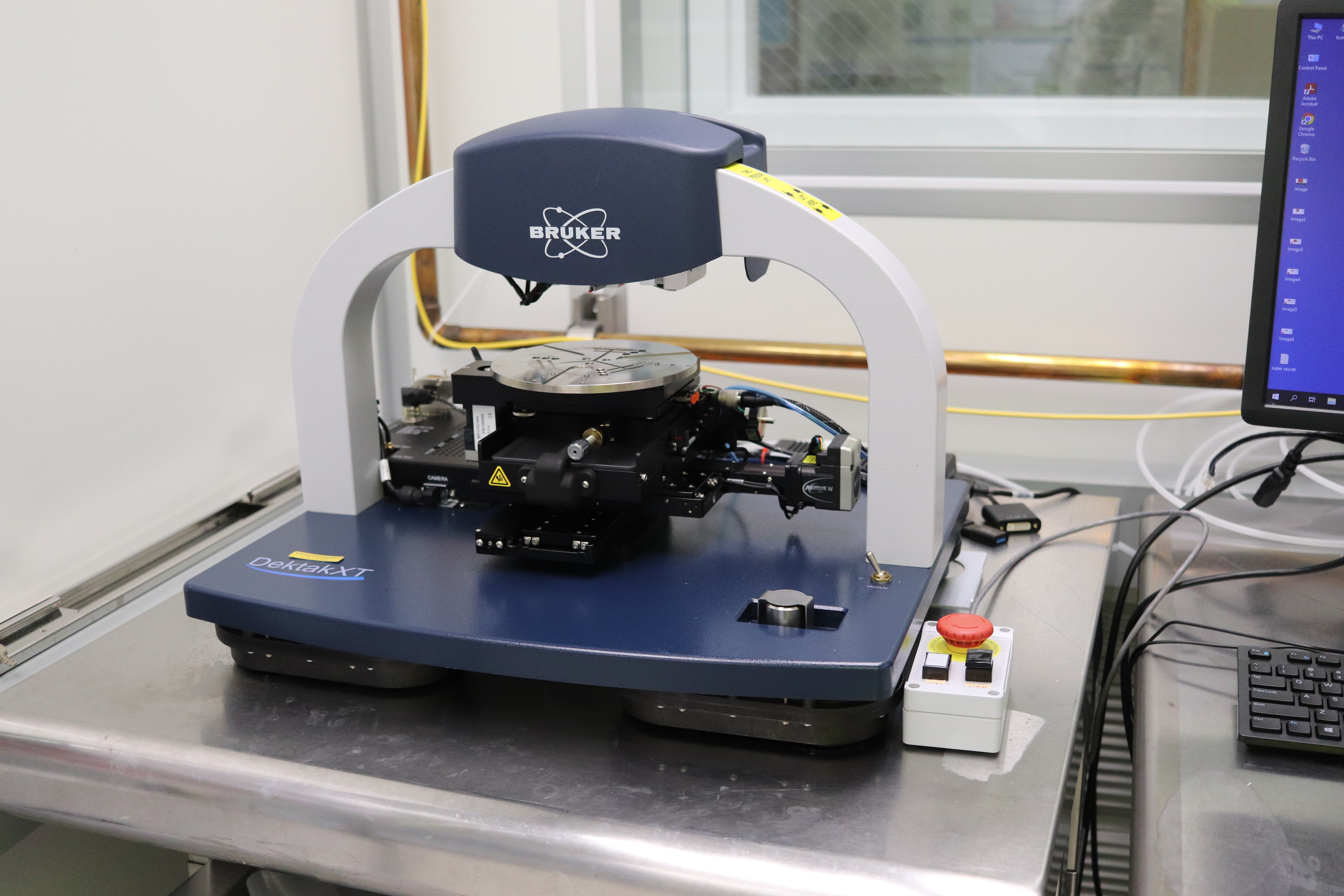
Description
The Dektak XTa is a stylus profilometer that measures surface height while scanning a stylus across the surface of a sample. It is a very robust, trustworthy measurement tool for getting the thickness of a variety of samples and for measuring roughness and curvature. Please see this website for more info.