Photo of 
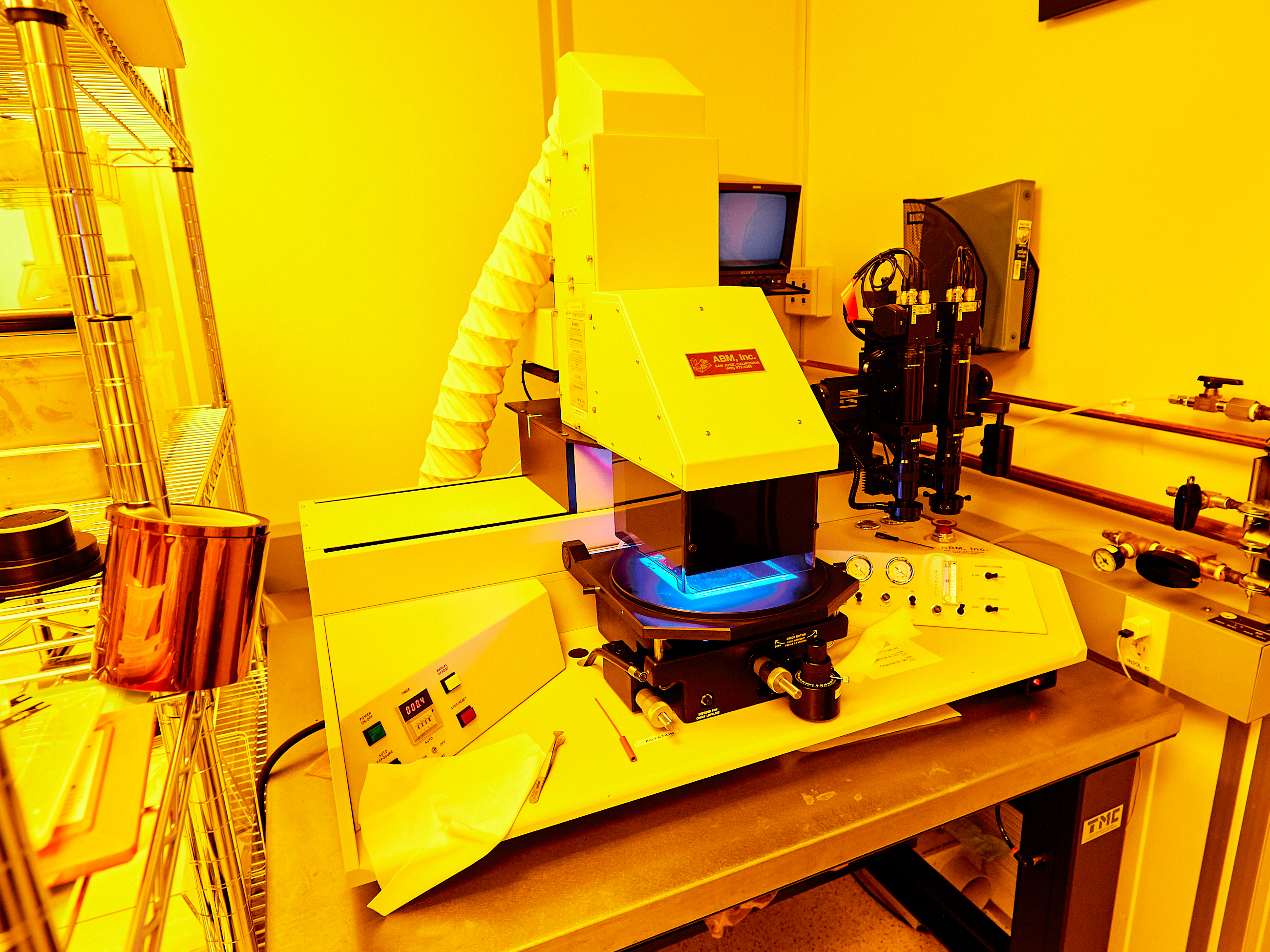
AB-M Contact Aligner

Description

The AB-M is our primary lithography tool using a broadband mercury arc lamp to expose photoresist. It is used for aligning substrates to masks, has an IR illumination system, and has a variety of filters for exposing different resist.

The ABM accepts 5" x 5" x 0.09" masks, We have at various times purchased wafers through:

https://www.photo-sciences.com/

https://www.photomaskportal.com/

https://www.compugraphics-photomasks.com/us/

Processes

  • AZ1512
  • AZ10XT
  • NR9-1500PY
  • SU-8 2002
  • SU-8 3050


Operating Manual

*Note that the instructions below may not contain the most recent updates. Please refer to the manuals printed and posted at the equipment.

Safety 

  • The ABM usesultravioletlight.Avoid exposureto skin and eyes.Never press any of the exposure buttons when the exposure system is in its home position. 
  • The ABMhasmoving parts.Makesure that nothing interferes with the movement of the exposure or alignmentsystems.Interfering withthemovement ofmechanical parts could damage the instrumentorcould causephysicalharm to the user.
  • Do not overcharge the UV lamp during start-up; this will burn out the bulb. 
  • The UV bulb contains mercury vapor and has the potential to explode. If this happens, evacuate the lab, inform staff, and wait at leastonehour before reentering.Do not attempt to clean up the bulb or mercury. 

Allowed Materials and Processes 

  • The ABM contact aligner is designed for single or multi-layer photolithography.AllUV sensitive resiststhathave been properly pre-baked should be safe to use. If you have any questions about the compatibility with new resists or substrates,contact staff to get approval. 
  • Backside alignment requires more stringent placement of alignmentmarks for proper use,please contact stafffor the specifications before ordering your masks. 

Restricted Materials and Processes 

  • Donot use wet chemicals or uncuredresistsonthe ABM. Theinstrument has sensitive componentsand has no ventilation hood to protectyoufrom fumes.If the ABM needs to be cleaned, spray IPA onto a cleanroom cloth and wipe the instrument. 

1. SETUP:

  1. If it is not already on, turnon the lamp powersupplyswitchand allow it to warm up for 5 minutes before turning on UV bulb.To turn on the bulb, press and hold the “Start” switch for approximately 2 seconds.You should see the indicator go up, then back down slightly. You should hear a “tick” sound, indicating that bulb has turned on.UV bulb usually takes about 30 minutes to reach full power,15mW/cm2,measured at 365 nm.  
  2. Turn on system vacuum and nitrogen by opening the valves attached to the wallto the right of the tool. 
  3. Switch on ABM power (red switch) and turn on ABM nitrogen switch.Verify that the flow is between 5 and 10 on themeter.The alignment lights andTV screens should turn on automatically with the red switch. 
  4. Check thatthere are no filters in placeand then loada filter ifnecessary. Unscrewthe two black thumbscrews on the front of the exposure system, removethe dark cover, and slidethe filter in from the left. Replace the cover and screw it back on. We have a long pass filter (PL-360-LP) and an I-line filter. 
  5. Verify that the gasket on the substrate chuck is at or below the level of the mask holder. If it is not, lower the substrate chuck until this condition is met. Otherwise the mask vacuum will not work. 
  6. Check that the x, y, and theta micrometers are approximately in the middle of their travel and that the substrate chuck is approximately centered in the mask holder opening. 

2. LOAD MASK: 

  1. Place your photomask onto the contact alignerwith the metal side downand push the mask vacuum button.Themnemonic is “brown goes down.”Check the vacuum gauge andattempt to slide the photomask with your hand toverifya proper seal. 
  2. Note: you may need to rotate the mask after you start alignment. During training you will learn how to rotate the mask. 

3. LOAD SUBSTRATE: 

  1. Raise the mask frameusing the switchand place your substrate onto the substrate chuck. There is a metal alignmentkeyto alignwiththe flat on your wafer. Make sure your wafer is not on top of this alignmentkey.If it is on thekeyinstead of next to it, the wafer could break. 
  2. Turn onthesubstrate vacuumand verifythe vacuum on the substrate vacuum gauge.
  3. Lower the mask frame.

4. PLANARIZE THE MASK AND SUBSTRATE: 

  1. Raise thesubstrate chuckso the separation of the wafer from the mask is~1mm.Presstheleveling button, then switch onthecontact vacuum,then releasetheleveling button,and finallyswitch offthecontact vacuum.This method is more reliable than using the clutched z-height knob.


5. ALIGN:

  1. Thedisplay monitors and illuminationshould already be on.The ABM is equipped with two cameras connected toadual-display on the rear of the instrument. There arethree differentilluminationsystems.One light system is thelight sources below thedisplaythat should come on automatically with the red switch.Next, there is asystemunderneath theright standard lamp.Thelastlighting system projectsIR lightthrough the wafer for backside alignment. Depending on the type of substrate you are working with,one light source may work better for alignment than the others.Weencourage you toexperiment.
  2. Align substrateandphotomask using the metal alignment peg for the flat of the waferor other waferalignment feature.Photomasksshould have alignment markers on the left and right-hand side of the mask.Camera 1 should align with the left alignment marker and Camera 2 should align with the right alignment marker.  
  3. Raise your substrate to less than 1 mm from the bottom of the photomask without touching. 
  4. Before moving the alignment system over,the photomask frame is in the down position and nothing is in the way of the movement of the alignment arm. 
  5. Flip the Alignmentswitch to move the cameras into position.  
  6. Move the objectives in an out using the knobs on the sides behind and above the objectives. 
  7. Align the cameras to the alignment marks on your photomask, by adjusting the verticalfocusknobs and the zoom knobs. 
  8. Align the substrate to the photomask using themicrometerson the contact aligner chassis. Alignment is complete when both markers on the substrate are aligned to the photomask. 
  9. Raise the substrate to make contact with the mask and verify that the wafer did not move substantially. 
  10. Turn on the contact vacuum and verify the vacuum on the gauge. 

6. BACKSIDE ALIGN (IR) 

  1. The ABM can do backside alignment with the IR lights. Thelamp(light source)for the IR is underneath thecontactalignerand needs to be switched on.   
  2. The light source is directed underneath the contact aligner throughflexible fiberoptics, which sometimes need to be pushed in gently to ensure proper illumination. 
  3. Alignment can be achieved in the same way as general alignment using the visible light. 

7. EXPOSE:

  1. Check that the exposure switchbelow the timerisin the ON position.This will cause the lamp shutter to open immediately when you move the light source from the HOME to the EXPOSE positionand expose for the time set on the TIMER.
  2. Adjusttheexposure time to ensure proper dosage for your resist and substrate. Be sure to check the manufacturer's protocol for recommendationsfor your specific resist.(Note: if you are using a new resist or a new thickness, we suggest performing an exposure matrix. Ask staff for help.)The last red digit is tenths of seconds. 
  3. Flip theLIGHT SOURCEswitchto move the lamp housing into position and expose the substrate for the set amount of time.Look away from the lamp to avoid exposure to eyes and skin. The lamp will make a loud click when the exposure starts and another click when the exposure stops. 

8. UNLOAD: 

  1. Home the exposure systemby toggling the LIGHT SOURCE switch to the HOME position.
  2. Turn the contact vacuum offand lower the substrate if necessary. 
  3. Raise the mask frame. It may need a little bump to get it moving. 
  4. Turn off the substrate vacuumand remove your wafer. If you are done, move on to SHUTDOWN. If you are exposing additional wafers, move to LOAD SUBSTRATE. 

9. SHUTDOWN 

  1. Turn offthesystem vacuum and nitrogen by closing the valves attached to the wall to the right of the tool. 
  2. Switch off ABM power (red switch)and turn off ABM nitrogen. 
  3. If you used a filter, remove it and put it away 
  4. Wipe down the contact aligner with IPA and clean room cloth. 

Troubleshooting 

  • The alignment and/or exposure switch does not move the appropriate arm into position. 
    • Check that the nitrogen and vacuum valves have been switched on. 
  • The exposure arm moves over but the lamp does not expose the substrate.
    • Check that thered ABM power switch has been flipped on.
    • Check that the tool isset to auto-exposurebelow the timer. 
    • Check that the green POWER ON/OFF button on the exposure panel is pressed in. The LED is broken, so it does not light up. 
  • It is impossible to get the wafers into focus. 
    • Check that the wafer is not on top of the alignment pin. 
    • Contact staff to re -center the focus. 
  • The contact vacuum is taking too long to release. 
    • Verify that the N2 switch is on and that the flow reads between 5 and 10 when the contact vacuum is off.